Photoelectric Sensors
The following information describes the basic forms of photoelectric sensors & controllers. Comments are made without considering the refinements in design of units which minimise the disadvantages and maximise the advantages.
Principles of Operation
LIGHT
Both visible light and infra-red light is used in P.E.Control. Each form of light has advantages and disadvantages generally depending upon the application.
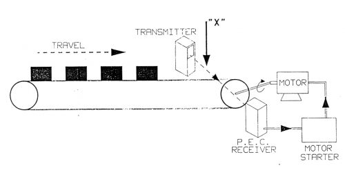
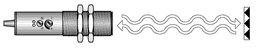
THROUGH BEAM
![]()
This is the simplest form in which a transmitter projects a beam directed at a receiver. When a body passes through, therefore breaking the beam, a signal is given by the receiver.
The advantages of this form are.–
- a) Reliability – particularly in dirty environments.
- b) Effective over long distances (typically 5 metres).
Disadvantages include:-
- a) High cost of units.
- b) High cost of installation.
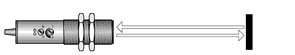
RETRO-REFLEX
![]()
Probably the most commonly used, these units have both the transmitter and receiver housed in a single unit, with the beam directed at a reflector. The reflector (a disc similar to a vehicle reflector) sends the beam back in the direction it came. The nature of the reflector is such that only course adjustment is necessary. A body breaking the beam causes a signal.
The main advantages of this form are:-
- a) Effective over long distances (typically 4 metres).
- b) Low cost installation requiring a single unit with a simple reflector mounting.
Disadvantages include:-
- a) False signals given off by semi or fully reflective objects passing through the beam. Typically beer kegs and glass bottles, and even shrink wrapped packing, particularly at close range.
POLARISED RETRO-REFLEX
These units are similar to the standard retro-reflex types but overcome the effect of false reflection by sending out a polarised beam which on hitting the reflector disc is rotated by 90 degrees. The beam then returns through a polarising filter which accepts only light from the same plane as that from the reflector. Light from a shiny object passing through the beam will therefore be 90 degrees out of phase and not pass through the receiving filter.
The advantages are:-
- a) The elimination of the “false signal” problem.
The disadvantages being:-
- a) More expensive units due to the extra costs involved with the polarising effect.
REFLEX TYPE
These units operate by the monitoring of the light reflected directly from an object. They normally need extra high gain circuitry because the light reflected from some objects is very low.
The main advantage is the absence of a reflector disc, which for certain applications may be difficult to locate and mount.
The disadvantages are that the operating distance is limited to approximately 2 metres maximum. The range depends on the types of surface being detected and the background may give greater reflection than the object.
ADJUSTMENTS
The following adjustments are provided within some photo electric units.
- a) Sensitivity or Gain Control
This allows the sensitivity of the photo-cell to be turned down to prevent the unit penetrating clear or translucent objects and hence giving a false signal. This applies to brewing and bottling lines and also to some plastic containers where at maximum sensitivity the beam may go straight through the object to be detected. Retro reflex units are usually better in these applications because the light beam has to pass through the object twice (send and receive).
In retro reflex applications, sensitivity may be reduced to prevent false triggering due to shiny objects (does not apply to polarised units where this problem does not arise).
In all cases, it must be noted that reducing sensitivity reduces the unit’s operating range.
- b) Time Delays
Many photo electric applications require time delays and if these are not fitted within the photo-cell, they must be fitted externally. It is important to remember that the specified delay relates to the reaction of the signal relay device to the change of state of the light beam and not to the speed of relay contacts (see diagram below).
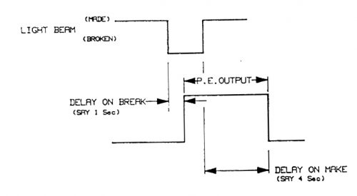
In this example, the output relay does not respond to the light beam being broken for a period of 1 second. It then operates and remains operated until 4 seconds after the beam remakes.
It is important to note that if the delay on break is set to longer than the time it takes a single object to pass, the output will not operate at all.
Many manufacturers include one or more of these features and some units have a single delay which may be switched to either delay on make or break.
The use of timers is illustrated in more detail under “Applications” later in this section.
PHOTO ELECTRIC APPLICATIONS
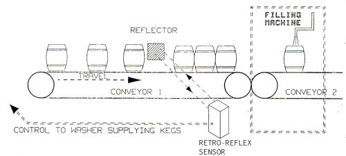
QUEUE BACK DETECTION
This application in its various forms is one of the most common uses for photo-cells. This example relates to beer kegs but the same problem arises in numerous different Industries.
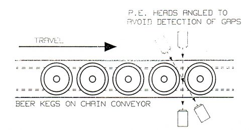
Kegs are passing down Conveyor 1, being filled and are then discharged onto Conveyor 2.
If the filling machine stops, say due to lack of beer, (such conditions should not occur) kegs would pile up against the machine eventually filling the conveyor and overloading Conveyor 1. The solution is to use a photo-cell with a time delay on beam break which ignores passing kegs because the beam is not broken for sufficient time to operate the relay. When the filler stops, kegs queue and touch and the beam is then broken permanently; timer times out and output is used to prevent any more kegs being fed onto conveyor.
When the filler restarts, the backlog clears, beam remakes and restarts the washer.
Note that Conveyor 1 runs continuously and the kegs skid upon it when stationary.
A polarised unit is used because of the danger of reflection from shiny kegs. An alternative would be a through beam system. In either case, the beam should be angled (not at 90 degrees) to avoid the risk of detection through slight gaps between kegs.
CONTROL OF CONVEYORS ON AIRPORT BAGGAGE HANDLING SYSTEM
Simple System (Ignore PE’s 2 & 4)
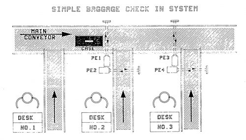
Cases are checked in at desks 1,2 & 3. They travel a short distance along a conveyor and are then deposited onto the main conveyor.
The function of the cells is to prevent collisions between cases as they arrive on the main conveyor.
Polarised retro reflex units are normally used since virtually any size, shape, colour or material may be used for baggage.
As the case travels down the conveyor, it breaks PE1 beam. The delay on make is used to prevent its relay operating until the front of the case is level with desk 2 conveyor. (Mechanical constraints invariably mean that the PE cannot be fitted next to the conveyor).
After the delay, the relay de-energises and this is used to stop desk 2 conveyor.
After the case clears the beam the delay on “make” starts timing. This allows the end of the case to clear desk 2 outlet after which the relay energises and restarts desk 2 conveyor. By this means, jams are prevented.
The only problem with this system is that the case passing down the main conveyor stops each desk in turn even if there is no danger of collision.
Practical System (Incorporating PE2 & 4)
PE1 & 2 also PE3 & 4 are interlocked so that the desk conveyors are stopped only if a case appears at 2 & 4 respectively at a point where collision is likely. Therefore both relays must operate at the same time to stop the conveyor.
Again, the time delays are used as detailed above.
DOOR OPENING SYSTEM
This is a slightly different scheme to normal in that the application is in a factory where pedestrians should use a side door and fork lift trucks use motorised double doors.

Retro reflex unit used because danger of false signal is minimal and would only open doors momentarily anyway. The unit is set to respond instantly when it “sees” reflector. Therefore the time delay on “make” is set to minimum.
On detection, the relay in the MAR operates and opens the doors. The delay on break is used to leave the doors open for sufficient time to allow the truck to pass.
Note that photo-cells used outside as in this case must be protected from driving snow and rain by means of hoods etc.
ONE WAY PERSONNEL DETECTION FOR SECURITY PURPOSES
In this case, the requirement is for a Company Security Officer to be aware of people entering into a building but not necessarily leaving.
PE1 is set to operate instantaneously.
PE2 incorporates a delay on make.
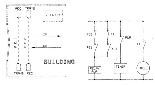
The circuit is as shown above:
If a person is leaving the building PE2 beam breaks first opening PE2 contact. The delay on make (say 3 seconds) allows the person to pass through PE1 closing and re-opening its contact and then PE2 re-closes. The circuit Ri has not been made and hence the bell does not operate.
When a person enters the building they break PE1 beam first which closes PE1 contact, relay 1 operates and latches via Ti (NC) and R1.
R1 also initiates a 1 second timer which rings the bell and then resets the system.
Note that Emitters and Receivers are alternated to prevent cross talk between adjacent heads. This is usually only necessary on transmitter/receiver units, retro reflex systems do not suffer from this problem.
AREAS WHERE GENERAL PHOTO-CELLS CANNOT BE USED
Photo Electric Guarding Systems
Photo electric units are now widely used to protect operators from dangerous machinery, typically press Brakes, Guillotines etc. These are highly specialised units conforming to Factory Inspectorate Regulations. A great deal of specialised knowledge is needed and the photo-cells are specially designed and constructed. Standard photocell units CANNOT be used for these applications.
Print Registration
Photo electric units are used for detection of a coloured mark on food wrappers etc., to ensure that the printing is in the correct position. The basic requirement is for a photo-cell to detect a printed mark on paper to indicate the position of the printing. A specialised colour detection unit is used.
Hazardous Areas
Where a gas hazard exists specially certified, suitably approved equipment MUST be used.
Our particular strengths are:-
1) Competitive Pricing
2) Fast Delivery
3) British Designed & Manufactured
4) Full service back-up (most manufacturers discard and replace with new)
Download our Full Catalogue.
© SYNATEL Instrumentation Ltd. MMXVII (o1/17)