Sensor Technology Guide – (simple)
Here are the very basics to different sensors types available.
No emphasis has been put on refinement to enable operation of sensors to improve.
This is a simple sensor technology guide.
PHOTO ELECTRIC SENSORS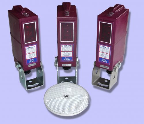
Which Type is Best?
This depends upon the application.
Ignoring requirements for output types, or built-in adjustable time delays.
For example, if it is a conveyor belt application:
1) Is power available on both sides of the conveyor?
2) When standing on the operator side of the conveyor system, is the background reflective or a lighter colour compared with the object to be detected?
Solutions:
Ideally (1) Through beam is best since the light beam travels one way across the conveyor (from emitter device to receiver device), and the object ‘breaks’ the beam.
However, it is not always possible to fit sensors on both sides of a system, due to close proximity of other objects or walls (2); or power not being available. In these instances two other options may prove useful.
a) Reflex systems. Which work by detecting the object itself and reflecting back the signal. Ideal if the background is far enough away or less reflective than the object being detected. Operating range is vastly reduced due to signal strength/reflection properties of object which affects performance.
b) Retro-reflex. Works similar to through beam sensors, in that it relies on the object ‘breaking’ the beam, however the emitter and receiver are built into a single housing and use a reflector to ‘bounce back’ the signal. This reduces operating range, since the beam travels twice the distance, there and back, plus there will be some signal loss within the reflector itself.
If highly reflective objects are being detected, the reflected signal back off the object can provide a false signal so that the system does not work reliably.
Polarised Retro-reflex sensor are available, which work by only detecting a reflected signal which has been through the prism of a reflector and is rotated by 90°, normal reflected light does not get rotated and so is ignored.
Also: Linked systems, where the emitter and receiver device work off the same controller, can have a PSR circuit built in (Phase Sensitive Receiver circuit) which only switches the receiver device on in sync with the pulse being emitted from the emitter device. The emitter device is pulsed on and off at a high frequency to help eliminate pick up from normal electrical lighting (50/60Hz) etc.
One infra-red source which is very difficult to overcome is the sun, since this emits a huge amount of infra-red. Consequently, shields fitted over the top of sensors and positioning the emitter device to look up at the receiver device, at an angle, helps to reduce interference.
Underspeed, Overspeed or Stopped Motion?
This depends upon the application.
Overspeed is rare and is effectively the opposite to underspeed, so won’t be discussed in detail here.
Underspeed:
Typically uses a proximity sensor (or mechanical input) ‘feeding pulses’ into a controller. As a shaft (with a protruding stud) rotates past the proximity sensor it generates a pulse. This pulse is ‘fed’ into the controller, providing the pulses are at the correct rate set within the controller, the output stays switched on. If the pulse rate falls below a pre-set level (typically 20% of normal running speed) then the output goes open circuit and indicates a fault condition.
The proximity sensor and associated underspeed circuit can all be built into one, cost effective unit (easy to install). Often, it also incorporates a timer on initial switch-on to allow machinery to achieve normal running speed before the sensor ‘monitors’ the pulses. Otherwise it would indicate an underspeed condition immediately it was switched on, facilitating the need for an external override circuit to allow machinery to start. Normally, when a fault condition occurs, the power would be removed from the sensor, when the system is re-started, the timer activates, allowing the machinery time to start up again,
Stopped Motion:
Are simpler in design/operation in that they are a timer circuit which is being re-set by an incoming sensor pulse. Providing, at least, one pulse is received within the time period the output stays on. If the pulses cease, the timer times out and the output switches off indicating a fault condition.
It should be noted that if the machinery being monitored was susceptible to ‘creeping’, if the target passed the sensor then the output would energise for the time period built-in. In this situation it would be wise to consider using an underspeed monitor, since slow creepage would be below its set speed and a true stopped state would definitely be underspeed. This is useful on fans in ovens, where rising heat can still turn the blades of the fan even when the machinery is off.
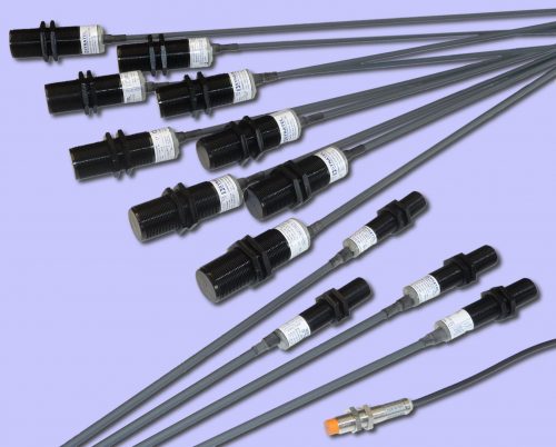
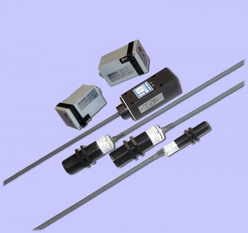
Inductive Proximity Sensor
Works only with metal.
Ideally suited for detecting Iron targets, but will also work with stainless steel, brass etc. at a reduced sensing range (typically 50/60%). Generally, the larger the coil producing the magnetic field, the longer the operating distance. Main operating principle is a magnetic field, which collapses when a metal target is presented. Electronic circuits make use of this change in state to provide output signals.
Capacitance Proximity Sensor:
Detects virtually any product.
These sensors will not detect through metal work, but can be placed against a plastic (or similar) side wall of a container, it can then be calibrated to ignore the side wall and only sense the product rising and falling on the other side of the container. Ideal for small hopper/container use to detect level.
Download our Full Catalogue.
© MMXVII Compiled by: Steve Wright