Inductive Proximity Sensors
The following information details general functionality of inductive proximity sensors and no comments are made considering the refinements in design of units which minimise the disadvantages and maximise the advantages.
PRINCIPLE OF OPERATION
Inductive proximity sensors are designed to work with metal object/targets without coming into contact. They are a relatively low cost, proven solution to a detection requirement. They are normally used to detect studs or targets on rotating or reciprocating machinery and provide an input into PLC’s, digital counting/speed displays, speed monitoring modules etc., and are more reliable than using mechanical actuators which can fail due to fatigue over time. They can be supplied in a variety of package styles, the most popular being (typically) 12mm, 18mm, 30mm diameter threaded bodies or 40mm square, DIN standard, limit switch style enclosures.
Fig.1
A magnetic field produced by a coil (Fig.1) and oscillator circuit, collapses when a metallic object is close enough, (a dampening of the oscillations), and it is this function which provides the basis of the inductive proximity sensor. Generally, the larger the coil and the higher the voltage, the longer the range of magnetism, but this can also induce problems which are mentioned further down in this article.
When a metallic object is introduced into the magnetic field it ‘collapses’, a suitable circuit with ‘upper’ & ‘lower’ thresholds can detect this collapse of magnetic field and it can be used to control an output.
Options could be to have an output normally de-energised (OFF), and energising (ON) when a metal target/object is introduced into the magnetic field, or vice versa.
Ferrous metal is ideally suited as a target (Fig.2), however non-ferrous metals (Stainless steel, brass etc.) can be used but with reduced operating range due to their weaker influence on the magnetic field.
Fig.2
Problems
The main criteria’s to be aware of are:
1) Maximum range: If a small coil is used and the range increased by increasing the voltage, the sensor can ‘latch on’. This can prove particularly troublesome where temperatures fluctuate and there is no temperature compensation in the circuit, since range can be affected by heat.
Fig.3
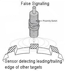
2) Speed: It should be noted that, generally, the magnetic coil emanates a magnetic field both sideways as well as in front of the sensor, if a shaft is rotating too quickly for the size of sensor and range being used, or the sensor is mounted too close to the targets such that is can detect leading and trailing targets at the same time, the magnetic field may not collapse and re-instate quick enough for all targets to be detected separately. Resulting in missed detection or latching circuit (Fig.3).
Our Advantages:
- British design & manufacture
- Quick delivery
- Works with all SYNATEL speed/stopped motion modules and digital displays.
- Approved versions available for explosive dust/gas hazard area use (ATEX EN 60079 & IECEx IEC 60079)
Disadvantges:
- non-approved units can be costly compared against some of the overseas competition, but can be more reliable.
See also: What is Certification?
Download our Full Catalogue.
This article © SYNATEL 2017, written and compiled by Steve Wright (o1/17)