Capacitance Probes (Digimatic)
Capacitance Probes
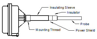
DIGIMATIC – DETAILS
Using the highly successful Digimatic probe as an example, we look at capacitance levels and their principle of operation.
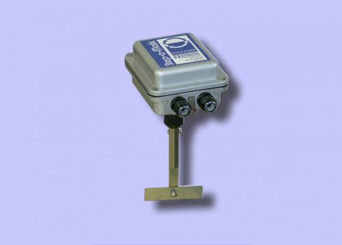
The SYNATEL Digimatic is a self contained, radio frequency (RF), capacitance level probe designed to provide a cost effective highly reliable means of monitoring level in all forms of silos, bins and hoppers. The Digimatic employs “Power Shield” technology to minimise the effects of material adhering to the probe, making it the first choice for sticky or viscous products such as flour, foundry sand and feeds containing molasses.
Digimatic has a digital display & membrane keypad to aid calibration and show/set process parameters. Calibration can be automatic or manual and once a calibration setting is determined, the same settings can be used for all probes in the same application.
The sensor has no moving parts, operates on 24V DC, 110 and 230V AC and provides a SPCO volt free relay contact output. An adjustable time delay is incorporated to minimise the effect of surging or splashing materials which would otherwise cause the output relay to chatter.
PRINCIPLES OF OPERATION
Digimatic is a capacitance probe which uses the capacitance of the material to determine whether or not the probe is covered.
Fig.1 (a) & (B)
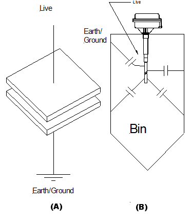
Fig.1 (A) shows two metal plates in close proximity but electrically separated. If a voltage is applied, a measurable electrical charge will be stored. The value of the charge will depend upon the surface area of the plates and their proximity. This principle is used for the tuning dial on old radios where multiple fixed and moving plates are moved to vary the surface area in proximity and hence the capacitance, to tune different stations.
If (say) a plastic slab of the same length and width as the steel plates above and having a height equal to the gap is slid between the plates, the capacitance measured will increase. This is due to a property of the plastic known as the dielectric constant. Air has a dielectric constant of 1 and all other materials (liquids, solids and gases) have a greater value. The capacitance difference between a covered and uncovered level probe is governed by this property.
The Digimatic measures the capacitance of the material by applying a high frequency (500 KHz) to the probe and uses a form of electronic AC bridge circuit to determine the value. For this reason, capacitance probes are sometimes known as R.F. (radio frequency) types.
Referring to Fig.1 (B), the live plate in fig 1 (A) is replaced by a solid rod and the earth plate by a circular metal bin. This is identical electrically to Fig.1 (A) but is coaxial (rather like a television aerial cable). In practice the container can be square, round, oblong or any other practical shape. The probe rod, normally round stainless steel, can in fact be any shape and any metal. The probe is shown mounted vertically in the centre of a bin but can be offset or mounted in the side, subject to certain rules.
The first point to note is that electrically the container is never empty, it is full of air, or some of the air is displaced and replaced by product. For this reason products which are mainly air are difficult or even impossible to detect. The classic example is expanded polystyrene packing material which is 95-98% air and cannot be detected by this means. Very light products with zero or low moisture contents can give problems and wood and its derivatives (cellulose, cellulose acetate etc) can be a problem.
In general but by no means always, the higher the weight per unit volume, the greater the effect on the probe and the more successful the application. In applications where materials are not sticky and have a satisfactory dielectric constant, most probes can be applied easily and simply. A typical application occurs in the molding industry where the requirement is to control the level of plastic granules in hoppers feeding molding machines (Fig.2).
Fig.2
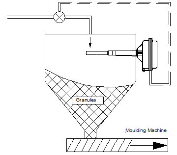
In this case a single Digimatic is used to turn on the fill mechanism when uncovered and stop it when covered. An internal, adjustable time delay is used to avoid the mechanism starting and stopping too frequently. In this application, which is an ideal one for almost any level probe, the material has a high dielectric, hence is easy to detect and as it empties, flows freely leaving the probe clear. If all materials were like this, the circuitry of the Digimatic could be dramatically simplified and all adjustments could be preset. Most types of level probe would work well in this application.
If a more difficult material is tackled the situation changes dramatically.
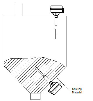
Fig.3 shows a flour bin and a probe has been used to detect low level. To enable it to operate as near to empty as possible, the Digimatic has been mounted in the angled section and is hence pointing slightly upwards.
Fig.3
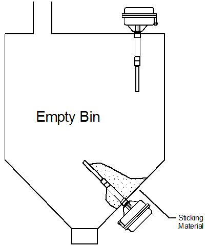
The nature of the product is such that it is very sticky and the mounting position means that a ‘flour bridge’ will exist as shown. Remember (1) the flour has excluded the air (2) the probe measures capacitance to earth and the nearest earth is the sidewall in which it is mounted. It will be apparent that this small amount of material can have a significant and at times disastrous effect on the probe. For this reason, all capacitance probes have some form of sensitivity adjustment to allow the effect of build up on the probe to be minimised. This adjustment is usually very limited and is normally an uncalibrated control knob or similar.
SYNATEL DIGIMATIC
The Digimatic has a unique digital setting system which gives a range of adjustment with recordable settings. Calibration of the Digimatic can be carried out automatically or manually.
 In automatic mode, it is simply a matter of pressing an “empty” button when the probe is uncovered and “full” button when the probe is covered. The unit takes account of the length rod and the surrounding metalwork on the empty setting and then the measured value of the material when the probe is covered. It then adjusts to 50% of the material value measured to give maximum allowance for material variation. The settings measured can be viewed at any time along with the actual trip value. In manual, the trip setting can be set to any desired value using raise and lower buttons. Both methods can be combined if required but in most cases the automatic method gives a simple “fit and forget” solution.
In normal operation, the Digimatic display shows process condition. Uncovered, this is the effect of the probe interacting with its surroundings and when covered, the same plus the effect of the material. With just a little experience, operators can glance at the display and check both the unit and the process instantly.
The sensitivity adjustment is used to calibrate the probe so that it detects the bulk of material covering it, but not the build up or residue left when the material leaves the probe. This can be difficult if the build up is substantial and for this reason, the Digimatic employs a further feature known as a “Power Shield”. The “Power Shield” is an active part of the circuit designed to ensure that the probe detects bulk material and not the residual material adhering to the probe
As explained previously, the basic capacitance measuring circuit operates by placing a high frequency signal on the probe rod. This signal radiates in all directions and measures the capacitance with respect to earth. The nearest earth in a metal bin is usually the side wall into which the probe is mounted, hence the probe is most sensitive to material at this point and it is the job of the “Power Shield” to minimise the effect of this material. See fig.4 for an explanation of the Digimatic features.
Fig.4
The “Power Shield” is energized with the same voltage frequency and phase as the probe and therefore no potential can be measured between the power shield and probe. This effectively creates a barrier or shield and prevents the probe from monitoring capacitance to the adjacent sidewall substantially minimising the effect of build up in the majority of cases. The means by which build up is overcome is shown in Fig.5.
Fig.5
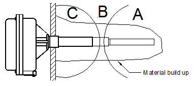
In practice, the build up will be one continuous lump but for explanation purposes, the probe is shown with build up separated into 3 sections.
Section A is the build up on the probe itself. This is ignored because the build up is insignificant in relation to the air beyond it (i.e. the majority of air between the probe and sidewalls has not been replaced) and hence the effect of this material is insignificant.
Section B is the build up between the probe and power shield. This is electrically “invisible” because both points are at the same potential and hence is ignored.
Section C is the build up between the power shield and earth. At this point a voltage gradient exists between the probe and earth creating a charged field which opposes that on the probe itself to minimise the effect of the material around the probe. The area of the field depends upon the conductivity of the material but is sufficient in the vast majority of cases to eliminate the effect of the build up. Cases where the power shield may not protect are detailed later. This feature combined with the automatic calibration facility makes the Digimatic an ideal, easy to use unit in most applications.
FAIL SAFE MODE
Fig.6
Under the normal circumstances shown in Fig.6 a high level probe is uncovered and a low level probe covered. In the event of a failure within the probe due typically to an interruption of supply, failure of the power supply circuit etc., the unit should ideally be “Fail Safe” and go into the alarm state. This is achieved by ensuring that with high level probes the relay is energized without material present and with low level probes the relay is energized with material present. A slide switch within the Digimatic is used to set the fail safe mode as high or low and this simply changes the relay from energized to de-energized and vice-versa.
DISPLAY, LED INDICATORS
The Digimatic incorporates a four digit 7 segment 0-9999 display to aid calibration and show process parameters. LED indication is also provided for power on, calibration mode and output.
SYNATEL Digimatic has a digital setting system, with automatic calibration and “power shield” technology.
MATERIALS DIFFICULT TO DETECT
As mentioned previously, very light materials or those containing substantial quantities of air may have insufficient capacitance change.
Very conductive materials have the effect of shorting out the power shield and probe reducing its ability to reject build up. This does not matter on a free flowing material which will fall off when it leaves the probe, sticky materials however may cling and give a false reading.
The only product to cause this problem generally is carbon black (used in the rubber industry) and typically, RF capacitance probes are not suitable for these applications. They can however, usually be used with great success in foundry sand despite the presence of carbon and conductive metal particles mainly due to their free flowing nature and the fact that most of the residue disappears when the vessel is emptied.
OTHER OPTIONS/PROBE TYPES
Rotating Paddles
Fig 7
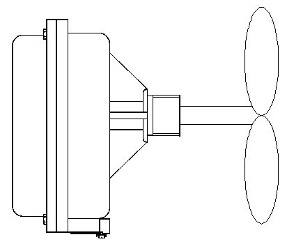
The paddle rotates driven by an electric motor until material covers it. Stoppage is detected by a variety of means both mechanical and electrical. This is a very common method in use.
Advantages
1) Easy to understand, simple operation.
2) Low maintenance and may be repaired on site.
Disadvantages
1) Moving parts.
2) Risk of failure of motor, gearbox and clutch.
3) Sometimes difficult to alter length.
4) Mechanically less robust than Digimatic.
5) Usually needs large diameter hole.
 Important – Most of the above disadvantages are overcome by the SYNATEL Step-a-Matic SML1(A) which uses a patented stepper motor direct drive which eliminates the gearbox and clutch and a folding paddle which allows insertion through a 1” BSP entry.
PRESSURE PAD
Fig.8
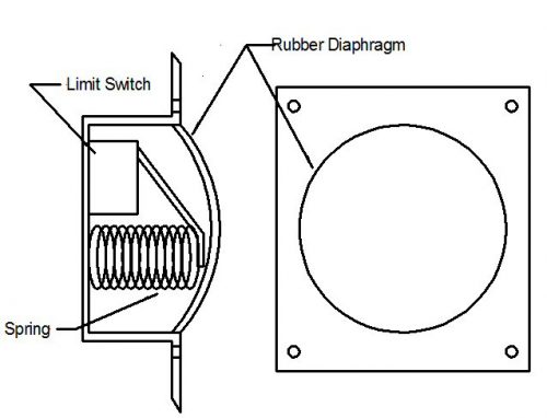
This method is fairly common, particularly on older installations because of its low cost. The unit is flange mounted in the side of a container and material pressure pushes the diaphragm into the micro switch.
Advantages
1) Cheap
Disadvantages
1) Large hole in bin/vessel/container.
2) Material may not create sufficient pressure to operate particularly at high level.
3) Diaphragm material damaged by product abrasion.
4) Difficult to set, spring tension; must be weak enough to detect material but strong enough to return diaphragm when uncovered.
ULTRASONIC TUNING FORK
Fig.9
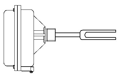
Tuning forks vibrate at high frequency until material contacts. Loss of oscillation is detected by electronic circuit.
Advantages
1) Easy to understand.
2) Generally reliable.
3) Works well in carbon black and similar materials.
Disadvantages
1) Costly, more expensive than Digimatic.
2) Difficult to alter length on site.
3) Mechanically weaker.
4) Material can jam in forks.
5) May not work in light material.
Note:
Capacitance Proximity Switches
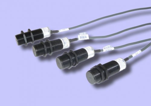 These are simple electronic capacitance switches generally in self contained plastic bodies. They are lowered from the top of the bin or screwed into the side.
They are a good replacement for diaphragm switches where material is non abrasive and dust build up insignificant. About 50% of Digimatic cost.
SYNATEL offer an innovative range of capacitance sensors which are ideal in straightforward applications. An abrasion shield is also available to avoid wear and tear of the sensor.
Advantages
1) Relative low cost.
2) No moving parts.
3) Simple fixing (1’ BSP).
4) Rod length may be altered on site.
5) Digital automatic setting plus power shield.
6) Universal voltage.
7) Integral timer.
8) ATEX/IECEx EN 60079 approved for explosive dust hazard area use.
Disadvantages
1) Difficult to understand operating principle hence slight fear of the unknown for non electrical people.
2) Early capacitance probes suffered drift, difficult setting procedures and build up problems. Some resistance still exists, particularly with older engineers even though this problem was eliminated many years ago.
3) Although approved (ATEX/IECEX EN 60079) for explosive dust hazard area use, unsuitable for gas hazard areas.
Some Common Questions and Answers
Q1) We put different materials in the same bins, do we need to calibrate each time?
A Generally no. Set the probe for the lightest material and the power shield will compensate. In some extreme cases resetting may he necessary. The most extreme case encountered has been a container alternating between Carbon Black (conductive) and French chalk (very fine powder).
Q2) Probe needs to be installed in the angled cone of a bin and hence point upwards. Does this matter?
A No – Digimatic may be installed at any angle.
Q3) A probe is to be installed vertically but until we fill with material, we don’t know the exact length. It will be between 0.5 metres and 2 Metres?
A Fit a 2 metre rod and cut it to correct length, determined by experimentation, using an ordinary hacksaw.
Q4) Can the rod be bent?
A Yes, it can be bent, drilled, extended or reduced. NB The rod, once fitted cannot be removed.
Q5) We wish to fit a low level probe in a 6m high bin. The sides are plastic coated and we don’t wish to drill them. How can this be done?
A Use a top mounted Digimatic with a 10 metre weighted wire rope probe cut to the desired length.
Q6) What if I can’t get the self contained Digimatic in due to space/vibration/temperature/access to calibrate.
A See details of remote version below.
DIGIMATIC RANGE
The basic Digimatic consists of the basic probe assembly plus one of the following probe rods.
1) Short rod (recommended for side entry)
2) 30cm Stainless Rod
3) 1m Stainless Rod
4) 2m Stainless Rod
5) l0m Stainless Wire Rope plus Weight
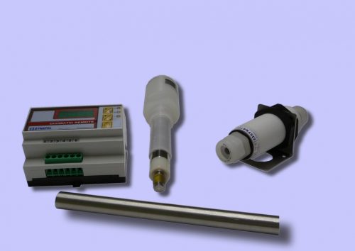 In areas where high temperature, vibration or space/access restriction exists, a remote version (DMR2A) may be used.
Various options are available but in each case, the system uses a remote controller, usually panel mounted which has all the same features as the self contained Digimatic. This works with a remote node local to or within the probe. The controller and probe can be up to 100Mtr apart and connected by ordinary 2 core screened cable. A range of probes are available for temperatures up to 250+ degrees Centigrade.
See also: What is Certification?
Download our Full Catalogue.
© SYNATEL Instrumentation Ltd. MMXIV